Voltage Drop Over Long Wire Runs 2026: NEC Rules & Calculation Guide
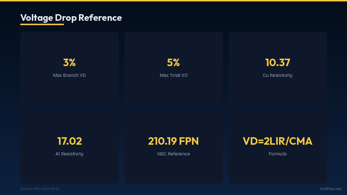
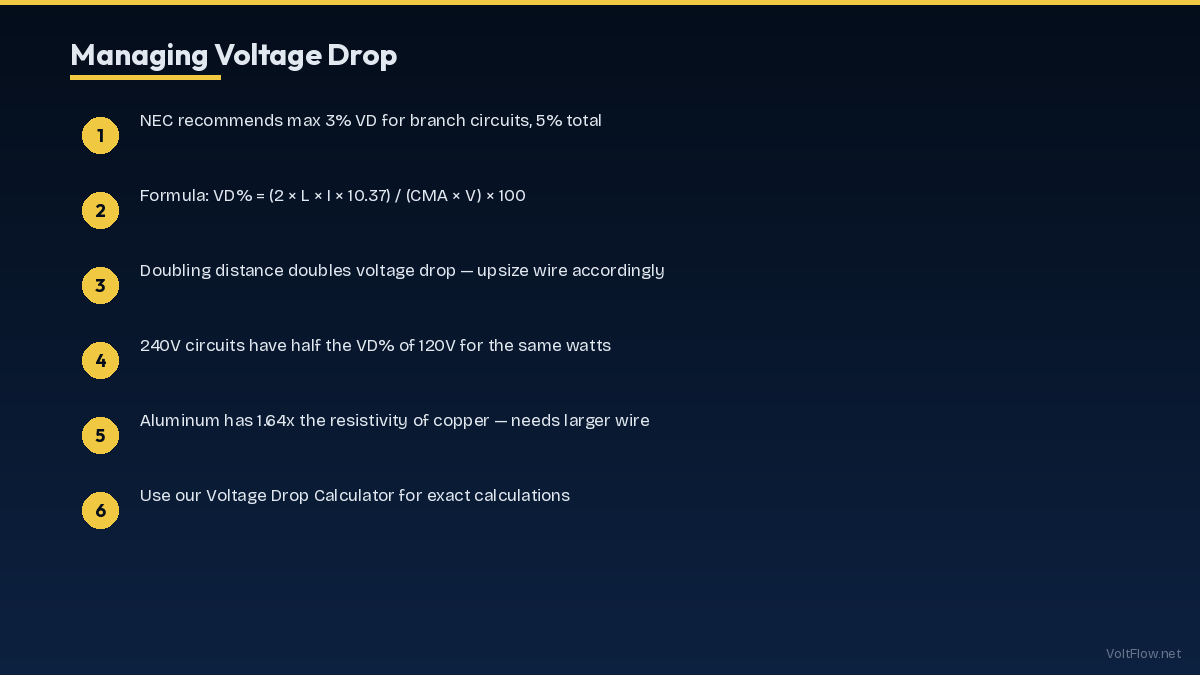
Voltage drop is the silent performance killer in electrical systems. Every foot of wire between your panel and a device adds resistance that reduces the voltage reaching the equipment. The NEC recommends keeping voltage drop below 3% for branch circuits and 5% total from service entrance to the farthest outlet. On a 120-volt circuit, 3% equals just 3.6 volts — enough to make motors run hot, lights dim, and sensitive electronics malfunction. This guide covers the voltage drop formula, NEC recommendations, wire sizing for long runs, and practical solutions.
Understanding Voltage Drop: Why It Matters
Voltage drop occurs because electrical wire has resistance. As current flows through the wire, some energy is lost as heat, reducing the voltage available at the load end of the circuit. The longer the wire run and the higher the current, the more voltage is lost. On short residential circuits of 20-30 feet, voltage drop is negligible, typically well under 1 percent. But on long runs of 75-200 feet that are common in workshops, barns, detached garages, pole-mounted lights, and well pumps, voltage drop becomes a serious concern that affects equipment performance, safety, and energy costs. Low voltage at a motor causes the motor to draw more amperage to maintain its power output. A 240-volt well pump motor receiving only 220 volts due to excessive voltage drop runs hotter, draws 8-10 percent more current, and wears out faster. Over the life of the motor, this can reduce lifespan by 30-50 percent and increase energy consumption by hundreds of dollars. Lighting circuits show voltage drop as dimmer-than-expected output. LED drivers are more tolerant than incandescent bulbs, but even LEDs can flicker or fail prematurely when voltage drops below their minimum operating range. Outdoor lighting runs of 100-200 feet to landscape fixtures or barn lights frequently suffer from voltage drop if undersized wire is used. Sensitive electronics like computers, network equipment, and medical devices may malfunction or shut down when voltage drops below their tolerance range, typically 5-10 percent below nominal. A 120-volt outlet delivering only 108 volts due to a 10-percent drop from a long, undersized wire run can cause unpredictable behavior in connected equipment. The NEC addresses voltage drop in Article 210.19(A) Informational Note No. 4, recommending a maximum of 3 percent for branch circuits and 5 percent total for feeders plus branch circuits combined. While these are recommendations rather than hard requirements, many jurisdictions enforce them as code requirements, and exceeding these limits creates measurable performance and safety problems regardless of code enforcement. Meeting the 3-percent recommendation on long runs often requires using wire one or two sizes larger than the minimum ampacity requirement. The extra wire cost is minimal compared to the equipment damage, energy waste, and performance degradation that excessive voltage drop causes.
The Voltage Drop Formula and How to Use It
The standard voltage drop formula for single-phase circuits is VD equals 2 times K times I times D divided by CM. Each variable represents a measurable property of the circuit. VD is the voltage drop in volts. K is the resistivity constant for the conductor material: 12.9 for copper and 21.2 for aluminum. I is the circuit current in amps. D is the one-way distance from the panel to the load in feet. CM is the circular mil area of the conductor, found in NEC Chapter 9, Table 8. The factor of 2 accounts for the round-trip distance because current flows through both the hot and neutral (or both hot) conductors. For 240-volt single-phase circuits with two hot legs, the formula is the same but you compare the result against 240 volts instead of 120 for the percentage calculation. For three-phase circuits, replace the factor of 2 with 1.732 (the square root of 3). Working through a practical example: you need to run a 20-amp, 120-volt circuit 100 feet from the panel to a workshop using 12-gauge copper wire. The circular mil area of 12 AWG is 6,530. Plugging into the formula: VD equals 2 times 12.9 times 20 times 100 divided by 6,530 equals 7.9 volts. As a percentage: 7.9 divided by 120 equals 6.6 percent. This exceeds the 3-percent recommendation by more than double, meaning 12-gauge wire is inadequate for this run despite being properly rated for 20-amp ampacity. To find the correct wire size, rearrange the formula to solve for CM: CM equals 2 times K times I times D divided by VD target. For a 3-percent maximum drop on 120 volts, VD equals 3.6 volts. CM equals 2 times 12.9 times 20 times 100 divided by 3.6 equals 14,333 CM. Looking at NEC Chapter 9 Table 8, the next wire size above 14,333 CM is 8 AWG at 16,510 CM. So this 100-foot 20-amp run needs 8-gauge copper wire to stay within 3-percent voltage drop, even though 12-gauge is the minimum for 20-amp ampacity. This is a common situation where voltage drop rather than ampacity determines the required wire size. For 240-volt circuits, the same wire gauge handles twice the distance because the percentage is calculated against 240 volts instead of 120. A 30-amp 240-volt circuit can run 130 feet with 10-gauge copper and stay under 3 percent, while a 30-amp 120-volt circuit with 10-gauge copper exceeds 3 percent at just 65 feet.
Quick-Reference Voltage Drop Table by Wire Size
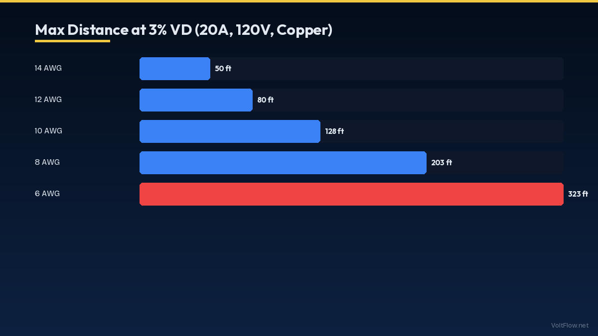
Rather than calculating voltage drop for every scenario, this reference table shows the maximum one-way wire run distance in feet for common circuits to stay within a 3-percent voltage drop using copper conductors. For 120-volt circuits at 15 amps: 14 AWG reaches 50 feet, 12 AWG reaches 80 feet, 10 AWG reaches 128 feet, 8 AWG reaches 203 feet, and 6 AWG reaches 323 feet. For 120-volt circuits at 20 amps: 12 AWG reaches 60 feet, 10 AWG reaches 96 feet, 8 AWG reaches 152 feet, and 6 AWG reaches 242 feet. For 240-volt circuits at 20 amps: 12 AWG reaches 120 feet, 10 AWG reaches 192 feet, 8 AWG reaches 305 feet, and 6 AWG reaches 485 feet. For 240-volt circuits at 30 amps: 10 AWG reaches 128 feet, 8 AWG reaches 203 feet, 6 AWG reaches 323 feet, and 4 AWG reaches 508 feet. For 240-volt circuits at 40 amps: 8 AWG reaches 152 feet, 6 AWG reaches 242 feet, 4 AWG reaches 381 feet, and 3 AWG reaches 480 feet. For 240-volt circuits at 50 amps: 6 AWG reaches 193 feet, 4 AWG reaches 305 feet, 3 AWG reaches 384 feet, and 2 AWG reaches 484 feet. These distances assume copper wire at 75 degrees Celsius. Aluminum wire has approximately 62 percent of the conductivity of copper, so multiply the copper distances by 0.62 to get aluminum distances, or use wire two sizes larger than copper for equivalent performance. For example, where 8-gauge copper works for a given run, you need 6-gauge aluminum. Temperature affects resistance and therefore voltage drop. Wire running through a hot attic in summer has higher resistance than the same wire in a cool basement. The table values above are conservative and include a safety margin for elevated temperatures. However, in extreme environments like rooftop conduit in the desert Southwest where temperatures inside conduit can reach 60-70 degrees Celsius, consider using the next larger wire size for additional margin. Conduit fill also affects voltage drop indirectly. Multiple current-carrying conductors in the same conduit reduce each wire ampacity due to mutual heating, which may require larger wire sizes that coincidentally improve voltage drop performance. Always check both the voltage drop calculation and the conduit fill derating calculation to determine the controlling requirement for wire size.
Common Long-Run Scenarios and Solutions
Several residential and light commercial scenarios frequently involve long wire runs that require voltage drop attention. Knowing the typical solutions for each saves time during the planning phase. Detached garage circuits are the most common residential long-run scenario. A garage 75-100 feet from the main panel needs a sub-panel fed by a properly sized feeder. For a 60-amp sub-panel at 100 feet using copper, 4-gauge wire keeps voltage drop under 3 percent. Using 6-gauge aluminum SER cable is a cost-effective alternative at roughly half the copper price. The sub-panel approach is better than running individual circuits because the feeder handles the voltage drop calculation once, and short branch circuits from the sub-panel have negligible additional drop. Well pump circuits frequently run 150-300 feet from the panel to the well head. A 240-volt, 10-amp submersible pump at 200 feet needs 8-gauge copper or 6-gauge aluminum to stay under 3 percent voltage drop. Many well installations use 10-gauge wire because it meets the ampacity requirement, but the resulting 5-7 percent voltage drop shortens pump life and increases energy consumption. Upgrading to 8-gauge copper adds approximately $100-$200 to the wire cost but extends pump life by years. Barn and agricultural building feeds commonly run 200-500 feet from the main service. At these distances, even heavy-gauge individual conductors become expensive. The economical solution is a dedicated transformer at the barn location, allowing the long run to carry higher voltage with proportionally lower current and voltage drop. For distances under 300 feet, a 100-amp feeder using 1/0 aluminum is typically adequate. Outdoor landscape lighting runs of 100-200 feet to low-voltage fixtures frequently suffer from voltage drop because installers use thin 16 or 18-gauge wire to save cost. At 100 feet on 16-gauge wire, a 12-volt landscape lighting circuit running 5 amps drops over 3 volts, a 25 percent loss that causes visibly dim fixtures at the end of the run. The solution is using 12-gauge direct burial wire for the main trunk and stepping down to lighter gauge only for short taps to individual fixtures. Alternatively, use a hub-and-spoke layout with multiple home runs from the transformer instead of a single daisy-chain run. EV charger circuits in driveways or carports located far from the panel present a growing challenge. A 50-amp circuit at 80 feet needs 4-gauge copper to maintain acceptable voltage drop, increasing wire cost by $200-$300 compared to the minimum 6-gauge required by ampacity alone. For carports beyond 100 feet, consider running a sub-panel closer to the charging location.
Copper vs Aluminum Wire for Long Runs
Choosing between copper and aluminum wire for long runs involves balancing cost, performance, and practical considerations. Both materials are safe and code-compliant when properly sized and installed, but their different properties make each better suited to certain applications. Copper wire has a resistivity constant of 12.9 ohms per circular mil foot, making it the better conductor. Copper connections are more reliable over time because copper does not oxidize as aggressively as aluminum. Copper wire is available in all gauges from 14 AWG down to 4/0 and beyond. For branch circuits inside walls where space is limited and connections must remain reliable for decades without maintenance, copper is the standard choice. The downside is cost. Copper wire prices fluctuate with commodity markets but typically run 2-3 times the cost of equivalent-ampacity aluminum. For a 200-foot, 60-amp feeder, 4-gauge copper wire costs approximately $600-$800 while 2-gauge aluminum costs $250-$350. Aluminum wire has a resistivity constant of 21.2 ohms per circular mil foot, meaning you need wire approximately two sizes larger than copper for equivalent voltage drop performance. Aluminum wire is about one-third the weight of copper, making it easier to pull through conduit on long runs. For feeders and service entrance cables above 6 AWG, aluminum is widely used in residential construction and is the standard for utility service drops. The historical concern about aluminum wiring relates to small-gauge aluminum branch circuits (15 and 20-amp circuits) used in homes built in the 1960s and 1970s. These connections were prone to loosening and overheating due to the different thermal expansion rate of aluminum compared to the brass and copper terminals they connected to. Modern aluminum wire above 6 AWG with appropriate AL-rated connectors and proper torque specifications does not share these problems. All modern electrical panels are rated for aluminum terminations on larger circuits. For long residential feeders to detached buildings, aluminum SER (Service Entrance Rated) cable is the most cost-effective choice. SER cable contains two insulated hot conductors, one insulated neutral, and a bare ground in a single jacket. A 2-2-2-4 aluminum SER cable rated for 90 amps costs roughly $2.50-$3.50 per foot compared to $5-$7 per foot for equivalent copper. On a 150-foot run, the savings of $400-$600 in wire cost alone makes aluminum the clear winner for budget-conscious projects. When using aluminum, always apply anti-oxidant compound (NoAlox or equivalent) to connections, use AL-CU rated devices and connectors, and torque all connections to manufacturer specifications. These practices ensure aluminum connections remain safe and reliable for the life of the installation.
Voltage Drop in Solar, EV, and Battery Systems
Modern homes with solar panels, EV chargers, and battery storage systems introduce new voltage drop considerations that traditional residential wiring never faced. These systems involve high currents over potentially long distances, making voltage drop calculation essential for proper system performance. Solar panel strings generate DC voltage that flows through wire from the roof to the inverter. The NEC limits voltage drop on the DC side to 2 percent for optimal energy production. A typical residential string at 40 volts and 10 amps running 50 feet from the array to a string inverter needs 10-gauge PV wire to stay under 2 percent drop. Using the standard 12-gauge PV wire that comes pre-attached to many panels may exceed the 2-percent recommendation on longer runs, reducing annual energy production by 1-3 percent. Over 25 years, that 1-3 percent loss represents thousands of dollars in lost production. Microinverters and power optimizers largely eliminate the DC voltage drop concern because they convert to AC or optimize voltage at each panel. The AC wiring from microinverters to the panel still requires voltage drop consideration but benefits from higher voltage (240V AC versus 30-50V DC) which naturally reduces percentage drop. For rooftop microinverter systems with a trunk cable run of 50-80 feet, standard 10-gauge AC wire is typically adequate. EV charger circuits are particularly sensitive to voltage drop because the charger communicates with the vehicle using pilot signals that reference the supply voltage. A Level 2 charger rated for 48 amps at 240 volts and installed 60 feet from the panel on 6-gauge wire experiences approximately 3.2 percent voltage drop at full load. This reduces the actual voltage at the charger to 232 volts, which causes the charger to deliver slightly less power and extends charging time by 3-5 percent. While this is not a safety concern, it reduces the convenience value of a high-power charger. Using 4-gauge wire for runs over 50 feet keeps the charger operating at its full rated output. Battery storage systems like the Tesla Powerwall, Enphase IQ, and Generac PWRcell require careful attention to wire sizing between the battery and the electrical panel. These systems can discharge at 30-60 amps continuously and may experience brief surge currents of 100 or more amps when starting large loads during a power outage. The wire between the battery and the panel must handle both the continuous load and the surge current with minimal voltage drop. Most battery manufacturers specify maximum wire run distances and minimum wire sizes in their installation manuals. The Powerwall requires 4-gauge minimum for runs up to 50 feet. Exceeding these specifications causes voltage sag during surges that can trip the battery protective circuits and shut down your backup power when you need it most. For integrated solar-plus-battery systems, the total system voltage drop budget must account for every segment: panels to inverter, inverter to panel, panel to battery, and battery back to critical loads during backup operation. Work with your installer to ensure each segment stays within its allocation and the total system drop does not exceed 5 percent under any operating condition.